k (MacSimski heeft pagina Repair Olivetti Programma 101 hernoemd naar Olivetti Programma 101 Repair: standardisatie reparatieverslagen) |
|||
| (4 tussenliggende versies door 2 gebruikers niet weergegeven) | |||
| Regel 2: | Regel 2: | ||
|Naam=Repair Olivetti Programma 101 | |Naam=Repair Olivetti Programma 101 | ||
|Eigenaar=MacSimski, | |Eigenaar=MacSimski, | ||
| − | |Status= | + | |Status=Pauze |
|Skills=mechanics, electronics, temper control | |Skills=mechanics, electronics, temper control | ||
|Samenvatting=Attempt to restore a Programma 101 to working order | |Samenvatting=Attempt to restore a Programma 101 to working order | ||
| Regel 33: | Regel 33: | ||
=== 16 okt 2014 15:49 (CEST) === | === 16 okt 2014 15:49 (CEST) === | ||
| − | Today we finally had the time to test the complete machine. and it's working, kind of. | + | Today we finally had the time to test the complete machine. and it's working, kind of. Lights come on and go off, keypresses are possible and there is a response on the reset button. but nothing has been printed yet. The strange behaviour could caused by a lazy 5 key. it will not rebound after a press and even when left untouched, it will sink into the keyboard again after a few strokes on other keys. I suspect a missing or broken spring, or a sticky mechanical latch. [[Gebruiker:MacSimski|MacSimski]] ([[Overleg gebruiker:MacSimski|overleg]]) |
=== 17 nov 2014 21:53 (CET) === | === 17 nov 2014 21:53 (CET) === | ||
| − | Mechanically the machine is ok (except the cardreader. to be fixed as soon as the machine is caclulating again) It takes a lot of presses on reset at power on to get the machine to show its ready light | + | Mechanically the machine is ok (except the cardreader. to be fixed as soon as the machine is caclulating again) It takes a lot of presses on reset at power on to get the machine to show its ready light, so something is still not right. I took a PCB out and noticed very dirty and rusty card-edges, so cleaning them with an eraser is now commencing. |
=== 18 nov 2014 13:39 (CET) === | === 18 nov 2014 13:39 (CET) === | ||
| Regel 45: | Regel 45: | ||
# still a mechanical timing problem | # still a mechanical timing problem | ||
# problem with the microswitches | # problem with the microswitches | ||
| − | # | + | # electrolytics on the various boards off spec or defective |
# Memory loop defective | # Memory loop defective | ||
| Regel 59: | Regel 59: | ||
=== 13 dec 2014 15:58 (CET) === | === 13 dec 2014 15:58 (CET) === | ||
| − | Today I noticed that sometimes after pressing the reset button, it takes a while to get a ready light. | + | Today I noticed that sometimes after pressing the reset button, it takes a while to get a ready light. Monitoring the leds connected to the 12 microswitches they behave normally, so my conclusion is now that the electronics are faulty, and probably the elcos. I desoldered one wire from the magneto memory (the red one near the rear of the machine. The ready light would not come on after repeatedly pressing the reset button. After reconnecting the wire, the light does come on after pressing reset. Another thing I did was replace the 6A fuse on the PSU PCB. This specific specimen had a lot of corrosion on its caps and wiggling it when turned on results in sparks. Definitely not good. After replacing the fuse, the ready light comes on more often than before. |
=== 13 dec 2014 17:00 (CET) === | === 13 dec 2014 17:00 (CET) === | ||
| − | I have replace all the elcos on the memory board: no inprovement. :-( | + | I have replace all the elcos on the memory board: no inprovement. :-( Strange thing is that sometimes the ready light comes on after almost a minute after the reset button is pressed. Could the memory be faulty? I set up my scope on the white wire of the memory module nearest the keyboard (memory input i think, noticing the high voltage) with the timebase of the scope setup on 0.2ms/div and this gives me one memorycycle. Signal is 2V/div and probe is on 1x div. Then I pressed reset repeatedly. |
[[http://youtu.be/llpwjGeldt0 Here]] a video of the result. | [[http://youtu.be/llpwjGeldt0 Here]] a video of the result. | ||
| Regel 69: | Regel 69: | ||
=== 15 dec 2014 11:25 (CET) === | === 15 dec 2014 11:25 (CET) === | ||
| − | GRMBH. Today I found out that I took a wrong pin for monitoring the AK signal. I have | + | GRMBH. Today I found out that I took a wrong pin for monitoring the AK signal. I have corrected this and will be reassembling the electronics module shortly to recheck the switches. But first I have to make some pictures of the boards and backplane. |
=== 16 dec 2014 13:37 (CET) === | === 16 dec 2014 13:37 (CET) === | ||
| − | Today Huge progress. Even as to say that I got the result of the square root of 6 out of it! But that was a long way to go. After I took the pictures and reassembled the machine, I took | + | Today Huge progress. Even as to say that I got the result of the square root of 6 out of it! But that was a long way to go. After I took the pictures and reassembled the machine, I took another look at the AK switch mechanism. As it turns out it was not working properly. Prodding some parts I discovered that the AK coding bar did not move freely, so the AK control latch did not return to its AK Control Bridge blocking position (doc "Olivetti_Programma_101_technical_manual", page 17, Figure 9). It took some time to find out that this coding bar was rubbing against some parts of the keyboard framework between the microswitch slides and the bearings of the bar in the plastic blocks were dry. With some drops of oil that was fixed. Put a drop of oil on the thick centerpart of the bar's profile contacting the frame (it's the part touched by legend 7 in fig. 9). The space is very constrained and you have only one or two milimeter between the slides and the frame support. The AK coding bar now moves freely and the triggering of the AK switch is prohibited in the first, but possible in the second revolution. |
[[Bestand:2014-12-16-848.jpg | center|thumb | 400px | where to apply oil]] | [[Bestand:2014-12-16-848.jpg | center|thumb | 400px | where to apply oil]] | ||
[[Bestand:2014-12-16-851.jpg | center|thumb | 400px | this bar should move freely when all the switch slides are down]] | [[Bestand:2014-12-16-851.jpg | center|thumb | 400px | this bar should move freely when all the switch slides are down]] | ||
| − | That solved a lot of the reset problems, but not all. :-( After a lot of prodding on connectors and wires things were still erratic. Sometimes the machine starts up with the error light burning and reset working as | + | That solved a lot of the reset problems, but not all. :-( After a lot of prodding on connectors and wires things were still erratic. Sometimes the machine starts up with the error light burning and reset working as expected, but on other occasions there would be no lights at all and no reaction to the resetting of the machine. As there are a huge amount of contacts in this machine (more that 850 alone in the electronics module) I decided that it was time for a proven concept: Percussive Maintenance. Using the plastic grip of a screwdriver I started hitting cards and other electronical parts gently while the machine was running with no lights on and Tada.wav: hitting the backplane resulting in the ready light coming on and the machine able to produce the square root of 6. Repeating the procedure after turning the machine off and on again did produce the same results. Well that narrows down the amount of contacts to check from 850 to about 840. Yeah... |
As I had cleaned the contact surfaces of the cards already that leaves only the counterpart on the backplane to clean and check, meaning taking the complete electronics module apart. That will be the thing for the next time. | As I had cleaned the contact surfaces of the cards already that leaves only the counterpart on the backplane to clean and check, meaning taking the complete electronics module apart. That will be the thing for the next time. | ||
| Regel 84: | Regel 84: | ||
=== 18 dec 2014 13:37 (CET) === | === 18 dec 2014 13:37 (CET) === | ||
| − | Today I had some time left to clean the contacts with a cloth wrapped around a piece of pcb soaked in alcohol. | + | Today I had some time left to clean the contacts with a cloth wrapped around a piece of pcb soaked in alcohol. A significant amount of dirt came out of the contacts of the backplane but matters did not inprove. :-( actually it got worse. now the machine will not produce a clear reset anymore. Fortunately today someone came up with a link to docs about the electronics: |
[http://www.museotecnologicamente.it/index.php?option=com_content&view=article&id=252&Itemid=986&lang=en museotecnologiamente.it] Unfortunately all in italian. And to make matters worse, the schematic drawings are not drawn in an standard way, so besides programming the P101 and Italian, I also have to learn the way they drew schematics in the day. O well... | [http://www.museotecnologicamente.it/index.php?option=com_content&view=article&id=252&Itemid=986&lang=en museotecnologiamente.it] Unfortunately all in italian. And to make matters worse, the schematic drawings are not drawn in an standard way, so besides programming the P101 and Italian, I also have to learn the way they drew schematics in the day. O well... | ||
| Regel 132: | Regel 132: | ||
=== 2 jan 2015 11:05 (CET) === | === 2 jan 2015 11:05 (CET) === | ||
| − | I have measured the wire gauge of the contacts and it turns out to be | + | I have measured the wire gauge of the contacts and it turns out to be 0.45mm. I have choosen to use phosphor bronze to make my own contacts. and try to find someone to apply a silver plating (if possible) |
=== 4 jan 2015 21:34 (CET) === | === 4 jan 2015 21:34 (CET) === | ||
| − | Yesterday I was lucky. | + | Yesterday I was lucky. Guitar strings are not useful as they are not made of phosphor bronze, but of steel and they can be wound with it. then I found a bead shop and they showed me "memory wire" that has the springlike appearance I was looking for and is silver plated. I bought some meters coiled up and today i made my first replacement of the wire. they even have better contact pressure than a good original one. Although the wire is 0,6mm, it fits the small space in the coneector housing, but only one wire can come though the hole in the pcb. So now to make 52 clips of the stuff... |
=== 11 jan 2015 23:13 (CET) === | === 11 jan 2015 23:13 (CET) === | ||
| Regel 144: | Regel 144: | ||
[[Bestand:P101_clips_size.jpg|400px|gecentreerd|thumb|measurement of the clips]] | [[Bestand:P101_clips_size.jpg|400px|gecentreerd|thumb|measurement of the clips]] | ||
| − | The holes in the backplane do not allow more than one wire coming through, so the shorter | + | The holes in the backplane do not allow more than one wire coming through, so the shorter end stays on the connector side of the pcb. The angle keeps that side of the clip from being pushed down during insertion of a card. |
[[Bestand:P101_clips_remake.jpg|250px|gecentreerd|thumb|first try]] | [[Bestand:P101_clips_remake.jpg|250px|gecentreerd|thumb|first try]] | ||
| − | The top one is still in good shape, the second my first attempt with soldered end. The third is a broken clip and the last one the second attempt in creating a clip. This one is made with the bendblock and was flat from the beginning. | + | The top one is still in good shape, the second my first attempt with soldered end. The third is a broken clip and the last one the second attempt in creating a clip. This one is made with the bendblock and was flat from the beginning. The first attempt went all directions and had to be flattend a lot. Length of the piece of wire is 65mm and cut beforehand. Contact pressure is even better then that of an original one. |
[[Bestand:P101_clips_bendblock.jpg|250px|gecentreerd|thumb|First bending block]] | [[Bestand:P101_clips_bendblock.jpg|250px|gecentreerd|thumb|First bending block]] | ||
| − | The block is just a small piece of wood with a nail hammered in and just sticking out of the wood as to keep the wire flat whilst bending. I used a regular big steel handsaw to make the gap. In hindsight a squarer piece of wood whould have been better, as i cannot make a marking for one of the bends, being more than 16mm (9mm clip inner + 180 degree bend radius around the pin). The angled mark bottom right with 5.5 near it is the angle for the first bend. | + | The block is just a small piece of wood with a nail hammered in and just sticking out of the wood as to keep the wire flat whilst bending. I used a regular big steel handsaw to make the gap. In hindsight a squarer piece of wood whould have been better, as i cannot make a marking for one of the bends, being more than 16mm (9mm clip inner + 180 degree bend radius around the pin). The angled mark at the bottom right with 5.5 near it is the angle for the first bend. Other bends go 90 or more degree around the pin. |
=== 07 feb 2015 23:55 (CET) === | === 07 feb 2015 23:55 (CET) === | ||
| − | Finally we have a fixed backplane again! | + | Finally we have a fixed backplane again! It took an afternoon of bending the clips and a evening/night to replace the broken ones on the backplane. |
| − | The bending methode I envisioned on the 11th of January was not that great and very cumbersome, so I had to think about a different approach. Finally I came upon a simple 3 stage bending process with 3 nails in a piece of wood and a round-nose plier. | + | The bending methode I envisioned on the 11th of January was not that great and very cumbersome, so I had to think about a different approach. Finally I came upon a simple 3 stage bending process with 3 nails in a piece of wood and a round-nose plier. Here are some pictures I took |
[[Bestand:Bending stage 1.jpg|400px|gecentreerd|thumb|Start of the bending]] | [[Bestand:Bending stage 1.jpg|400px|gecentreerd|thumb|Start of the bending]] | ||
| Regel 175: | Regel 175: | ||
[[Bestand:Backplane during repair.jpg|400px|gecentreerd|thumb|Setup on the table]] | [[Bestand:Backplane during repair.jpg|400px|gecentreerd|thumb|Setup on the table]] | ||
| − | I made a extraction tool with a piece of iron wire to hook behind the loops of the broken clips to get them out. | + | I made a extraction tool with a piece of iron wire to hook behind the loops of the broken clips to get them out. It's a bended double piece of wire with two small hooks at the end. It is visible on the setup picture just above the replacement clip next to the pliers. |
| + | |||
| + | === 11 feb 2015 22:10 (CET) === | ||
| + | |||
| + | Failure. :-( | ||
| + | |||
| + | That is what I got. The clips are not right. They are too thick and scratch the surface of the boards. Besides that, after reassembly of the machine, we get no reaction of the lights on the machine. None whatsoever. So it is possible that even more clips have failures now. I have to find a better wire and maybe even a shop who can make about 1000 of them and give them a gold plating... | ||
| + | |||
| + | For now I have shelved the project for the time being. Don't expect an update soon. Sorry | ||
== Electronics == | == Electronics == | ||
| − | Before testing the machine, | + | Before testing the machine, an overhaul of the powersupply is very inportant. I've checked the various capacitors and reformed them, and only the big 5000uf 50v capacitor was bad. To test the powersupply, we need a dummyload of about 10ohm at 24V, to get a voltage reading of around 20v on the powerline. Pins are p1f and p1m. I've used two car headlight bulbs rated at 60watt each and put them in series. another 21W 12v car bulb was loaded on the minus 10v rail (p3f and p1m). Voltages are fine. |
== Links == | == Links == | ||
Huidige versie van 4 jan 2016 om 09:55
| Project: Repair Olivetti Programma 101 | |
|---|---|
| Naam | Repair Olivetti Programma 101 |
| Door | MacSimski |
| Status | Pauze |
| Madskillz | mechanics, electronics, temper control |
| Doel / Omschrijving | |
| Attempt to restore a Programma 101 to working order | |
| Alle Projecten - Project Toevoegen | |
Our Olivetti Programma 101 has been sitting idle in a cellar for at least 10 years. Because of the way the machine is built and its age, all the mechanical parts have gummed up. Grease and oil have turned into a tough goo and the various belts have deteriorated. Checking and fixing the machine is only possible after a thorough cleaning, application of fresh lubricating agents and replacement of all the belts. Afterwards, we will be able to proceed with checking the electronics of this calculator.
Mechanics
The mechanics are divided into several assemblies, fixed to each other and the chassis with sometimes hard to reach screws. It is the earliest known instance of a RISC processor ("Ridiculous Italian Screw Construction"). Some screws are almost unreachable; for some screws you need to stick a very long screwdriver completely through the assembly to reach it.
The major units are:
- Keyboard assembly.
- Printer assembly.
- Servo assembly
- Card reader assembly.
- Motor.
- Main cooling fan.
Progress
After a first internal inspection it was clear that all the mechanical parts had gummed up by old grease and oil and that all the belts save one had turned into goo. Fortunately the machine was not tampered with or "repaired" by an amateur. We proceeded by taking the machine apart when we encountered the now famous "Ridiculous Italian Screw Construction". Especially the card reader and the electronics cage are fitted in this fashion. I made a long flat srewdriver from a piece of long iron to reach for the deep placed screws. Finding the screw underneath the powersocket took some time as well.
The machine taken apart I focused on getting the mechanics working again. The separate assemblies were taken and submerged in Nebol grease cleaner. Belts were removed with care not to spoil the clean surroundings and the path cleaned with Dasty grease remover. Getting the motor running smoothly again turned out to be a strange thing. To get to the gummed up brass bearings, we took apart the motor and cleaned the shaft and bearing with brake-cleaner. After reassembly everything was smooth, but returning the next day we found a gummed up motor on the bench. After a few attempts we discovered that the brass is porous and a piece of oil drenched felt is behind the bearing, regreasing the shaft overnight. So a thorough submerge in nebol fixed that for good.
The pinchroller for the magcards was a different problem. It had gummed up so badly and deformed beyond measurement. 11mm,12mm? we don't know. for now I've cleaned the rod of its remains and took a measurment on the other intact roller. As it is connected to the pinchroller with a belt and pulleys of the same diameter, I think it could well be the right size: 12mm. The pichroller was restored with car gas tubing with 6mm internal and 12mm outer diameter. the pinchroller rod is 5mm diameter, so shrinktubing is used to fill the gap. Works perfectly.
That was the last mechanical hurdle so rebuilding has started now. Only one belt needs to be recreated, but that can only be done after the motor is back on the chassis. When the machine is back in one piece, we will focus on the electronics, starting with the power supply. Fortunately people at the Danish Datamuseum are also working on their 101 and have a rather good repairlog: http://datamuseum.dk/wiki/Olivetti/Programma_101/Revive
16 okt 2014 15:49 (CEST)
Today we finally had the time to test the complete machine. and it's working, kind of. Lights come on and go off, keypresses are possible and there is a response on the reset button. but nothing has been printed yet. The strange behaviour could caused by a lazy 5 key. it will not rebound after a press and even when left untouched, it will sink into the keyboard again after a few strokes on other keys. I suspect a missing or broken spring, or a sticky mechanical latch. MacSimski (overleg)
17 nov 2014 21:53 (CET)
Mechanically the machine is ok (except the cardreader. to be fixed as soon as the machine is caclulating again) It takes a lot of presses on reset at power on to get the machine to show its ready light, so something is still not right. I took a PCB out and noticed very dirty and rusty card-edges, so cleaning them with an eraser is now commencing.
18 nov 2014 13:39 (CET)
Cleaning the contacts did not improve matters. although they were indeed very dirty in some places, I do not notice a better working machine. Then thinking over the possibilities, there are a few things left to check:
- still a mechanical timing problem
- problem with the microswitches
- electrolytics on the various boards off spec or defective
- Memory loop defective
1. and 2. are detectable by using a logic probe on the 12 switches.
3. is by checking with an ESR meter or reforming them.
4. check with a oscilloscope.
As the beaglelogic logic probe is still not operational, but the outcome of the tests influences the working of the machine a lot, I will be focussing on the beaglebone for the time being.
13 dec 2014 15:58 (CET)
Today I noticed that sometimes after pressing the reset button, it takes a while to get a ready light. Monitoring the leds connected to the 12 microswitches they behave normally, so my conclusion is now that the electronics are faulty, and probably the elcos. I desoldered one wire from the magneto memory (the red one near the rear of the machine. The ready light would not come on after repeatedly pressing the reset button. After reconnecting the wire, the light does come on after pressing reset. Another thing I did was replace the 6A fuse on the PSU PCB. This specific specimen had a lot of corrosion on its caps and wiggling it when turned on results in sparks. Definitely not good. After replacing the fuse, the ready light comes on more often than before.
13 dec 2014 17:00 (CET)
I have replace all the elcos on the memory board: no inprovement. :-( Strange thing is that sometimes the ready light comes on after almost a minute after the reset button is pressed. Could the memory be faulty? I set up my scope on the white wire of the memory module nearest the keyboard (memory input i think, noticing the high voltage) with the timebase of the scope setup on 0.2ms/div and this gives me one memorycycle. Signal is 2V/div and probe is on 1x div. Then I pressed reset repeatedly. [Here] a video of the result.
15 dec 2014 11:25 (CET)
GRMBH. Today I found out that I took a wrong pin for monitoring the AK signal. I have corrected this and will be reassembling the electronics module shortly to recheck the switches. But first I have to make some pictures of the boards and backplane.
16 dec 2014 13:37 (CET)
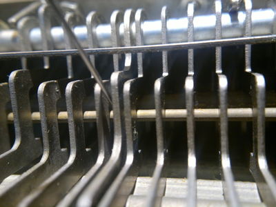
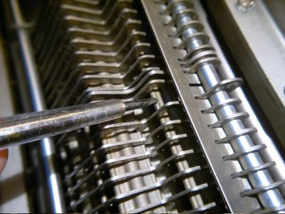
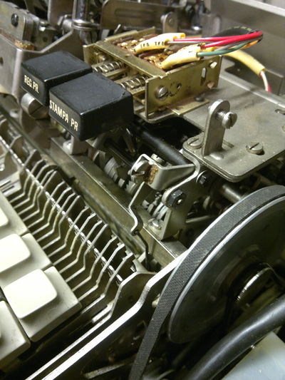
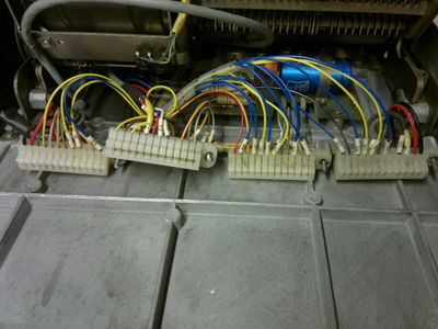
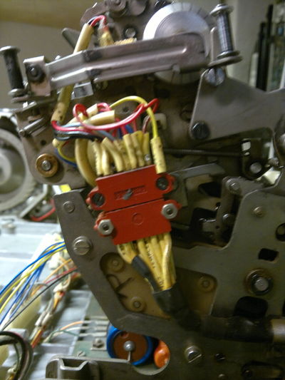
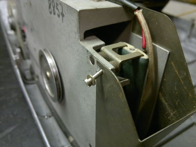
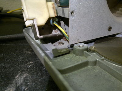
Today Huge progress. Even as to say that I got the result of the square root of 6 out of it! But that was a long way to go. After I took the pictures and reassembled the machine, I took another look at the AK switch mechanism. As it turns out it was not working properly. Prodding some parts I discovered that the AK coding bar did not move freely, so the AK control latch did not return to its AK Control Bridge blocking position (doc "Olivetti_Programma_101_technical_manual", page 17, Figure 9). It took some time to find out that this coding bar was rubbing against some parts of the keyboard framework between the microswitch slides and the bearings of the bar in the plastic blocks were dry. With some drops of oil that was fixed. Put a drop of oil on the thick centerpart of the bar's profile contacting the frame (it's the part touched by legend 7 in fig. 9). The space is very constrained and you have only one or two milimeter between the slides and the frame support. The AK coding bar now moves freely and the triggering of the AK switch is prohibited in the first, but possible in the second revolution.
That solved a lot of the reset problems, but not all. :-( After a lot of prodding on connectors and wires things were still erratic. Sometimes the machine starts up with the error light burning and reset working as expected, but on other occasions there would be no lights at all and no reaction to the resetting of the machine. As there are a huge amount of contacts in this machine (more that 850 alone in the electronics module) I decided that it was time for a proven concept: Percussive Maintenance. Using the plastic grip of a screwdriver I started hitting cards and other electronical parts gently while the machine was running with no lights on and Tada.wav: hitting the backplane resulting in the ready light coming on and the machine able to produce the square root of 6. Repeating the procedure after turning the machine off and on again did produce the same results. Well that narrows down the amount of contacts to check from 850 to about 840. Yeah...
As I had cleaned the contact surfaces of the cards already that leaves only the counterpart on the backplane to clean and check, meaning taking the complete electronics module apart. That will be the thing for the next time.
18 dec 2014 13:37 (CET)
Today I had some time left to clean the contacts with a cloth wrapped around a piece of pcb soaked in alcohol. A significant amount of dirt came out of the contacts of the backplane but matters did not inprove. :-( actually it got worse. now the machine will not produce a clear reset anymore. Fortunately today someone came up with a link to docs about the electronics: museotecnologiamente.it Unfortunately all in italian. And to make matters worse, the schematic drawings are not drawn in an standard way, so besides programming the P101 and Italian, I also have to learn the way they drew schematics in the day. O well...
27 dec 2014 10:28 (CET)
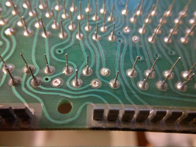
Well, after taking a closer look at the contacts, I found out that some of them are broken and are unable to press hard against the card edge contacts. That could be the main reason for the intermitted reset results. The contacts are made of bended wire with a gold coat and the break occurs in one of the two sharp bends in the middle between the two contact faces.
Translating the documents has started.
28 dec 2014 20:18 (CET)
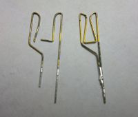
Here a broken clip on the left, and a spare one on the right. After careful examination of PCB 08, I found four edgeconnector pins not in use. Those clips are now in place of the four broken ones on the backplane. Not all the clips are examined yet. Testing is done with a piece of PCB, one finger wide, and inserting it in the edge-connector at every single connection. If the friction is weak, the clip is a suspect. Desoldering it is the only way to check and maybe correct it. Oh well, it's cold outside anyway. :-)
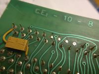
Where the spare clips came from. I suspect there are more to get on other board positions.
29 dec 2014 22:32 (CET)
GRMBH. I found 52 bad clips on the backplane, Some are broken, some just weak. Oh well, on the 925 available clips, that is not much. :-) replacing the broken ones with spares can be difficult now.
| Board | Free clips |
|---|---|
| 01 | 0 |
| 02 | 0 |
| 03 | 0 |
| 04 | 0 |
| 05 | 0 |
| 06 | 0 |
| 07 | 0 |
| 08 | 12 |
| 09 | about 9 |
That is a total of 21 clips for replacement. The clips on the memory board (09) are not entirely clear, as the space surrounding the pins on the pcb is very tight and paint has been applied on this board close to the edge connectors. I have to find a way to restore contact pressure without replacing the bunch.
2 jan 2015 11:05 (CET)
I have measured the wire gauge of the contacts and it turns out to be 0.45mm. I have choosen to use phosphor bronze to make my own contacts. and try to find someone to apply a silver plating (if possible)
4 jan 2015 21:34 (CET)
Yesterday I was lucky. Guitar strings are not useful as they are not made of phosphor bronze, but of steel and they can be wound with it. then I found a bead shop and they showed me "memory wire" that has the springlike appearance I was looking for and is silver plated. I bought some meters coiled up and today i made my first replacement of the wire. they even have better contact pressure than a good original one. Although the wire is 0,6mm, it fits the small space in the coneector housing, but only one wire can come though the hole in the pcb. So now to make 52 clips of the stuff...
11 jan 2015 23:13 (CET)
Here some pictures I took during the fabrication of the new edgeconnector clips.
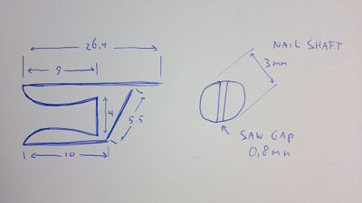
The holes in the backplane do not allow more than one wire coming through, so the shorter end stays on the connector side of the pcb. The angle keeps that side of the clip from being pushed down during insertion of a card.
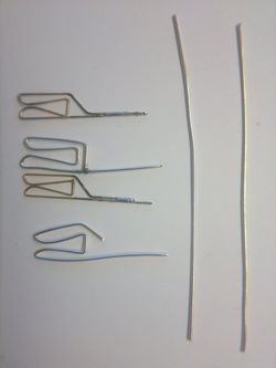
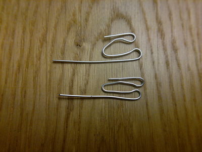
The top one is still in good shape, the second my first attempt with soldered end. The third is a broken clip and the last one the second attempt in creating a clip. This one is made with the bendblock and was flat from the beginning. The first attempt went all directions and had to be flattend a lot. Length of the piece of wire is 65mm and cut beforehand. Contact pressure is even better then that of an original one.
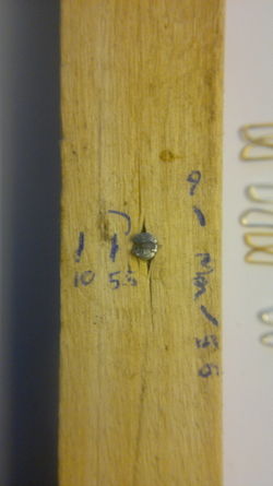
The block is just a small piece of wood with a nail hammered in and just sticking out of the wood as to keep the wire flat whilst bending. I used a regular big steel handsaw to make the gap. In hindsight a squarer piece of wood whould have been better, as i cannot make a marking for one of the bends, being more than 16mm (9mm clip inner + 180 degree bend radius around the pin). The angled mark at the bottom right with 5.5 near it is the angle for the first bend. Other bends go 90 or more degree around the pin.
07 feb 2015 23:55 (CET)
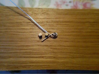
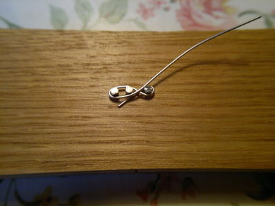
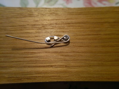
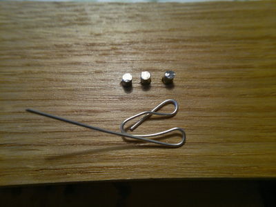
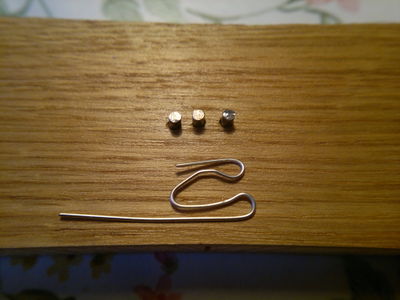
Finally we have a fixed backplane again! It took an afternoon of bending the clips and a evening/night to replace the broken ones on the backplane. The bending methode I envisioned on the 11th of January was not that great and very cumbersome, so I had to think about a different approach. Finally I came upon a simple 3 stage bending process with 3 nails in a piece of wood and a round-nose plier. Here are some pictures I took
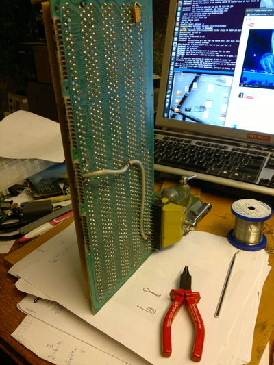
I made a extraction tool with a piece of iron wire to hook behind the loops of the broken clips to get them out. It's a bended double piece of wire with two small hooks at the end. It is visible on the setup picture just above the replacement clip next to the pliers.
11 feb 2015 22:10 (CET)
Failure. :-(
That is what I got. The clips are not right. They are too thick and scratch the surface of the boards. Besides that, after reassembly of the machine, we get no reaction of the lights on the machine. None whatsoever. So it is possible that even more clips have failures now. I have to find a better wire and maybe even a shop who can make about 1000 of them and give them a gold plating...
For now I have shelved the project for the time being. Don't expect an update soon. Sorry
Electronics
Before testing the machine, an overhaul of the powersupply is very inportant. I've checked the various capacitors and reformed them, and only the big 5000uf 50v capacitor was bad. To test the powersupply, we need a dummyload of about 10ohm at 24V, to get a voltage reading of around 20v on the powerline. Pins are p1f and p1m. I've used two car headlight bulbs rated at 60watt each and put them in series. another 21W 12v car bulb was loaded on the minus 10v rail (p3f and p1m). Voltages are fine.
Links
- The Datamuseum in Denmark is restoring their 101.
- page with signalpaths
- more pictures in out galley


