Uit Hack42
| (Een tussenliggende versie door dezelfde gebruiker niet weergegeven) | |||
| Regel 1: | Regel 1: | ||
{{Project | {{Project | ||
|Naam=OneWireSwitch | |Naam=OneWireSwitch | ||
| − | |Eigenaar=BugBlue | + | |Eigenaar=BugBlue |
| − | |Status= | + | |Status=Afgerond |
|Skills=solderen, slijpen, zagen, schroeven, programmeren | |Skills=solderen, slijpen, zagen, schroeven, programmeren | ||
|Samenvatting=Onewire switch bouwen op basis van een oude switch | |Samenvatting=Onewire switch bouwen op basis van een oude switch | ||
}} | }} | ||
| + | == The idea == | ||
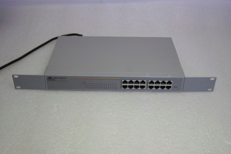
| + | * Take a (broken) 19" switch | ||
| + | * Saw off the exces part of the switch you don't need (everything except the ports and the PCB directly underneath) | ||
| + | * figure out the pins | ||
| + | ** Pin 1: ground | ||
| + | ** pin 2: data | ||
| + | ** pin 3: VCC | ||
| + | * get a rasterized printboard and some headers | ||
| + | * make a shield for your arduino | ||
| + | ** Connect all the data pins to the data cables for the ports (16 in this case) | ||
| + | ** solder 16 resistors (1k or 4k7) from 5V VCC to all the datapins | ||
| + | ** solder 5V and GND | ||
| + | * screw the arduino to the board | ||
| + | * connect the shield to the arduino | ||
| + | * insert a USB cable | ||
| + | * upload the software | ||
| + | * close the case | ||
| + | * apply stickers | ||
| + | * place the switch in the rack | ||
| + | * If any time is left you can connect some leds | ||
| + | |||
| + | == The software == | ||
| + | <pre> | ||
| + | please type in here... | ||
| + | </pre> | ||
| + | |||
== Gezocht == | == Gezocht == | ||
Nyancat stickers. Ter hoogte van 1U :) | Nyancat stickers. Ter hoogte van 1U :) | ||
Huidige versie van 19 aug 2012 om 19:07
| Project: OneWireSwitch | |
|---|---|
| Naam | OneWireSwitch |
| Door | BugBlue |
| Status | Afgerond |
| Madskillz | solderen, slijpen, zagen, schroeven, programmeren |
| Doel / Omschrijving | |
| Onewire switch bouwen op basis van een oude switch | |
| Alle Projecten - Project Toevoegen | |
The idea
- Take a (broken) 19" switch
- Saw off the exces part of the switch you don't need (everything except the ports and the PCB directly underneath)
- figure out the pins
- Pin 1: ground
- pin 2: data
- pin 3: VCC
- get a rasterized printboard and some headers
- make a shield for your arduino
- Connect all the data pins to the data cables for the ports (16 in this case)
- solder 16 resistors (1k or 4k7) from 5V VCC to all the datapins
- solder 5V and GND
- screw the arduino to the board
- connect the shield to the arduino
- insert a USB cable
- upload the software
- close the case
- apply stickers
- place the switch in the rack
- If any time is left you can connect some leds
The software
please type in here...
Gezocht
Nyancat stickers. Ter hoogte van 1U :)

