(→Todo) |
k (Lurwah heeft pagina Telex hernoemd naar Gebruiker:Hack42/Telex) |
||
| (3 tussenliggende versies door 3 gebruikers niet weergegeven) | |||
| Regel 1: | Regel 1: | ||
{{Project | {{Project | ||
|Naam=Twitter Telex | |Naam=Twitter Telex | ||
| − | |Eigenaar=BugBlue,Stoneshop,eightdot,denz | + | |Eigenaar=BugBlue, Stoneshop, eightdot, denz |
| − | |Status= | + | |Status=Afgerond |
|Skills=Electronics,Telex protocol,Baudot Code,Programming,Soldering,Mad ideas | |Skills=Electronics,Telex protocol,Baudot Code,Programming,Soldering,Mad ideas | ||
|Samenvatting=Connecting the Siemens Fernschreiber Telex to Twitter and paypal | |Samenvatting=Connecting the Siemens Fernschreiber Telex to Twitter and paypal | ||
}} | }} | ||
__TOC__ | __TOC__ | ||
| + | |||
| + | {{flickr|m|4|random|hack42 Twelex}} | ||
== Background == | == Background == | ||
Huidige versie van 21 mei 2024 om 20:45
| Project: Twitter Telex | |
|---|---|
| Naam | Twitter Telex |
| Door | BugBlue, Stoneshop, eightdot, denz |
| Status | Afgerond |
| Madskillz | Electronics, Telex protocol, Baudot Code, Programming, Soldering, Mad ideas |
| Doel / Omschrijving | |
| Connecting the Siemens Fernschreiber Telex to Twitter and paypal | |
| Alle Projecten - Project Toevoegen | |
| www.flickr.com - tags:hack42 Twelex (random) (max: 4) |
Background
Twittering is cool, Retro™ hardware is cool and so RetroTwittering obviously is cool². Which is why BugBlue decided to hook our Siemens T-1000 Fernschreiber (telex) up to the internetz. All it required was some signal conversion electronics, python coding and some deep knowledge of ancient protocols.
We've written down the building steps for those who wish to read the #42 RetroTweets the way they are intended.
Step 1: Find the telex
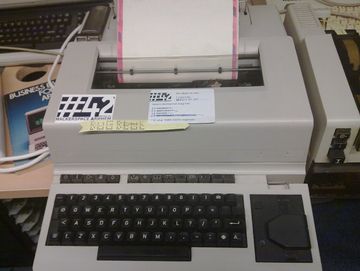
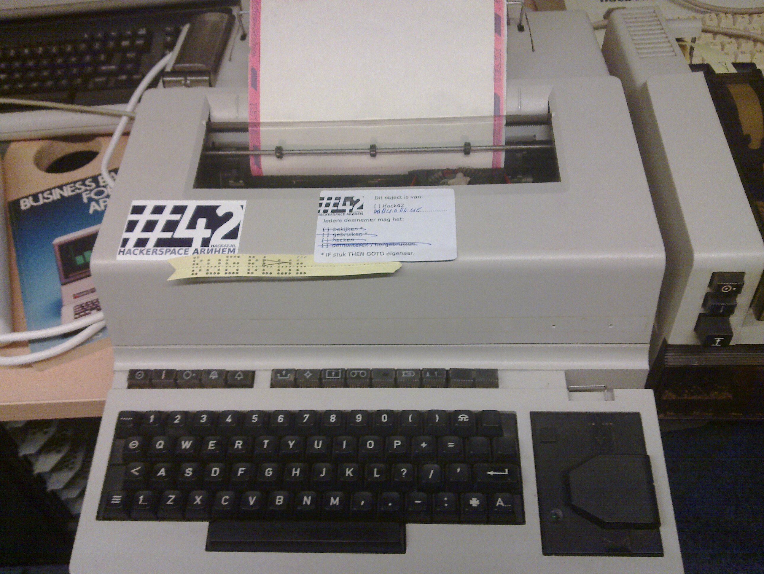
We just happened to have a late 1970's model telex standing around doing nothing but being pretty, well sort of. Since we started working on it we've seen a number of such machines on Ebay. These are pretty hefty machines though, you might want to look somewhere close enough to pick it up.
- Found it
Step 2: Test if it works
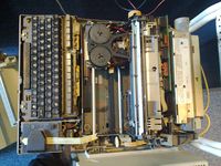
Check if all the keys work and behave like they should. Also test the internal interfaces, the punch tape writer, punch tape reader etc etc etc.
- Creative people do creative tests.
Step 3: Build a circuit
The telex interface is based on the current loop principle at a speed of approx. 50 baud. To communicate over a serial line to a modern day computer we need some electronics to generate the current loop and read the return signals. We opted for a USB-to-Serial adapter but, as this does not offer speeds as low as 50 baud, the control signals are used instead of the TX and RX pins.
For this step you need some knowledge about electronics, optocouplers, voltages, power supplies, resistors and more stuff BugBlue did not know about.
- However some smarter people do know this stuff.
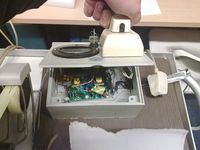
Step 4: Build a nice box to house the electronics
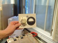
Since having 230Volt open on the table is not really on everyones wishlist some housing is a big +1, an amp meter was thrown in for authentic looks.
- The result of eightdots work
Step 5: Write some code
With TX and RX out of the picture some code is needed to do bitbanging magic. The code is written in python, for no other reason than pySerial being the first hit on Google for "serial set dsr". A bit of insight in the timings (50 baud, 1 bit is 20ms) and some coding skills do work very well.
Step 6: Test the code (and tweet it)
- Tweeting pictures is a lame hack, but the code wasn't ready yet. Link to real tweets.
Step 7: Finish and polish it
This needs to be done.
Step 8: Document
A schematic would be nice
- Here is a nice schematic - hope we don't blow components.
This schematic does connect the ground from serial to the ground from the external 5V power supply. This does violate standards, however the RS232 standard is also violated in the software, see below. this is not a problem, as long as the 5V supply isn't connected to anything else.
Simple explanation about this schematic:
- Create a 40mA ~ 78V current loop (should be 40mA @ 120V, however 2 NT1 ISDN power supplies only gave us 78 Volts)
- first violation of protocol standards
- If you want to transmit data you have to break the loop: set DTR low in the software for 20ms and you've transmitted 1 MARK, set DTR high for 20ms and you've transmitted 1 SPACE
- Transmit bits using DTR (active low): second RS232 violation
- If you close the mechanical lock you set CTS high, used in software to check if the user wants to type
- CTS with only 5 volts? Violated RS232 again (marginally)
- If the telex sends a MARK this will make DSR go low.
- Inverting it to real RS232 standard is work, we're lazy. Violates again.
- If you set RTS high it will close the relay and switch poles to the telex connection. This powers down the T1000.
- Violates telex standards and RS232 standards. A nice win.
- The 78 Volt and 5 Volt/RS232 circuits are completely seperated from each other. Just to save hardware for a smelly burning death.
The ampere and volt meter are only there for the authentic old-look. It's nice to be able to see what data we transmit.
Total standards violations: 7 with only 5 RS232 pins used, who needs TX or RX?
Credits
- Hack42 - Telex
- Stoneshop - Circuits design,schematic,hardware (meters, lock, box)
- eightdot - electronic supplies, design, box, soldering
- denz - Soldering
- BugBlue - software, soldering
- vreemt - punchtape-art
Todo
- Change software to interface with paypal
Order paper and inkDone.
Later
- Create coin collector to interface with computer
- Change software to interface with coin collector
- Find a nice 'who are you' line
- Change the 'Here-is' identity to 'Hack42'
